What’s the Difference Between a Primary Flow-Measuring Station and a Secondary Flow-Measuring Station?

Figure 1: Parshall Flume
Before answering that question, it is probably best to define what constitutes a primary flow-measuring station and a secondary flow-measuring station. Both are used to measure flow in an open channel, such as a stream or a ditch, but a primary station measures flow through a known and controlled structure. A secondary station measures flow in a stream channel or ditch under natural channel conditions so the flow is not being measured through a known and controlled structure.
So, what’s the difference between the two types of flow-measuring stations? Since a primary station measures flow through a controlled structure an equation that relates flow depth to actual flow has already been developed. Therefore, if the depth of flow is measured, the flow associated with that depth can be easily looked up and a primary device provides a very accurate estimate of the surface water flow in the channel or ditch.
Conversely, with a secondary station, because flow is being measured in a natural channel that may have an irregular shape, vegetation growing in the channel, a combination of earthen materials and rocks, and sinuosity, it is more difficult to obtain accurate flow measurements. As opposed to a primary flow-measuring station where flow can be obtained simply by reading the depth of flow at the device, flow measurements at secondary stations have to be conducted manually and then calibrated with a known equation, as I will discuss below.
PRIMARY FLOW-MEASURING STATIONS
Typical primary flow-measuring devices include Parshall flumes (Figure 1) and types of weirs (Figure 2). For each of these devices there are prepared tables showing the relationship of water depth to flow. Therefore, once installed properly, flow measurement at primary devices is very simple and can be read manually by installation of a staff gage with the primary device or it can be set up with a stage-discharge recorder (SDR) or datalogger with a transducer for automatic readings with time. An example of a hydrograph obtained from an SDR is presented in Figure 3.

Figure 2: Rathbun Weir, designed by LWS on a tributary entering Bear Creek Lake in California.

Figure 3: Bear Creek Gage Hydrograph (CO DWR).
What is extremely important is to install the device properly, including the positioning and the location. For Parshall flumes it is important that the flume is installed level in all directions and that the outlet section be situated such that the flow can exit the flume without backing up flow. It is important that there is laminar flow entering the flume so that when flow goes through the constriction in the flume midsection, flow is accelerated and becomes supercritical, causing a hydraulic jump. If the flume becomes submerged in the throat and/or diverging sections due to backflow conditions downstream of the flume it will not measure flow correctly. Therefore, the downstream end of the flume should have sufficient fall to prevent backflow but also be reinforced with rip-rap to prevent erosion of the channel.
For the installation of weirs, it is important to understand the flow range that needs to be measured, as simple weirs can be installed or compound weirs. Typical weirs are V-notch (the center section in Figure 2), rectangular, and trapezoidal (Cipoletti) weirs (the outer section of the weir in Figure 2). There are also different types of crests for weirs, e.g., sharp-crested, broad-crested (as in Figure 2), or ogee-shaped crests. Weirs can be very versatile relative to measuring a large flow range by constructing a compound weir, such as the one shown in Figure 2. The V-notch weir measures lower flows; however, during runoff periods with significantly higher flows, the Cipoletti weir can measure these flows. As such, the total flow is the combined flow through the V-notch and the Cipoletti weirs.
When installing weirs, it is necessary that they be installed level, but the crest of the weir must also be installed at a level high enough that it doesn’t get submerged by the water downstream, i.e., free flow over the weir crest must be maintained at all times. For flow measurements with a weir, the staff gage or recording device must be placed far enough upstream that it is outside the flow nappe (sheet of water) going over the weir crest but within the pool created by the weir. This distance will vary based on the size of the weir and the flow characteristics being measured; a typical rule of thumb is that flow measurement needs to be located upstream, 3 to 5 times the maximum expected water level elevation behind the weir. Flow is then calculated using the depth of water, i.e., the difference between the maximum water level elevation behind the weir but in the weir pool and the crest elevation of the weir.
The locationing of the flume or weir is also a critical component to obtaining accurate flow measurement data. Since both devices will act as constrictions to the natural flow in the channel or ditch, it is important to minimize the effect on flow, so sizing the device to the channel to be measured is paramount. Any primary device should be located in a straight stretch of the channel to be measured and centered on the flow section so there is not a major constriction in the flow path. It is also important that there not be any flow bypassing the device, either beneath it or around it.
SECONDARY FLOW-MEASURING STATIONS
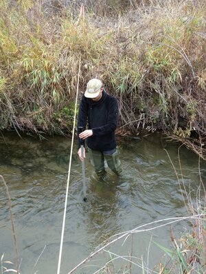
Figure 4: LWS taking streamflow measurements with current meter.
A secondary flow-measuring station is typically referred to as a “rated section.” This is because flow is being measured in a natural stream channel or a ditch and, because the flow has to be calculated manually using a current meter that measures flow velocity, one measurement only provides the relationship of flow depth to flow for that singular measurement. As such, to develop a rating curve that defines the relationship of depth to flow requires multiple manual readings at differing depths and associated flows. Once a number of measurements have been made, a depth-flow relationship can be developed, i.e., a rated section. Figure 4 shows a photo of a LWS field crew conducting a flow measurement with a current meter (an instrument for measuring the velocity of flow of a fluid in a stream).
To estimate flow at a rated section, a tape measure or similar distance-measuring device, is strung across the channel to be measured. Then the flow cross-section is subdivided into segments, with the flow velocity being measured at each segment. In this way, velocity is measured in each segment so variations in flow velocity across the section are accounted for, and then flow is calculated as:
Q = A * v
Where, Q = flow (cfs)
A = cross-sectional area of the segment (ft2)
v = average velocity in the segment (ft/sec)
Once the flow has been calculated for each segment using the formula above, the total flow is calculated as the sum of the flow in each segment. It is important to obtain flow measurements at variable depths over time to then prepare a rating curve for flow through the secondary flow-measuring section. To then calibrate this rated section, it is advisable to compare the measured data against the Manning’s equation, which is used to calculate flow in open channels. The Manning’s equation is:
v = 1.49/n (R2/3) (S1/2)
Where, v = flow velocity (ft/sec)
n = Manning’s roughness factor (dimensionless)
R = hydraulic radius (ft)
S = hydraulic slope (ft/ft)
The Manning’s equation can be used to calibrate the rating curve, i.e., make adjustments to measured flow to better estimate flows through open channels where primary flow devices are not warranted or are not applicable.
Which type of flow-measuring device is appropriate? The answer is very site-specific. LWS has installed many primary flow-measuring devices, including flumes and weirs, as well as having conducted numerous flow measurement plans, including establishment of rated sections as well as gain/loss studies. If you have questions regarding the need for flow-measuring equipment and what would be appropriate for your particular situation, please give us a call (303-350-4090) or send us an email.
Bruce Lytle, P.E. bruce@lytlewater.com
Chris Fehn, P.E., P.G. chris@lytlewater.com
Dan Rowe dan@lytlewater.com