Groundwater Well Design and Completion
Groundwater is a vital freshwater resource primarily used for drinking water and irrigation; it can be extracted through a well (production well). Installing a groundwater production well requires a site-specific design appropriate for the purpose of the well and the site hydrogeology. To evaluate the design, research should be conducted to provide a good idea of what to expect in terms of the site hydrogeology. This blog presents a general concept of how a production well is designed and completed.
Once the location for the intended well has been determined, the next step is to make sure that everything is legal. How much are you allowed to pump? Are you tapping into not-nontributary water in the Denver Basin? How do you apply for a permit and what kind of permit? In Colorado you can visit the Division of Water Resources website to find out more, or contact LWS for assistance.

After getting the required permit to install a well, the drilling process can begin. It is crucial to initially confirm that there are no buried utility lines or subsurface structures at the drilling location. Clearance of utilities can be provided by the driller or the engineer.This step should be taken on all well sites as there is always the possibility of buried utilities, even in remote areas.
While there may be information on the general hydrogeology of the area, many times conditions will vary from those thought to be present at the site to those that are actually at the site. Therefore, a field engineer or geologist is often the expert on-site to determine the final well depth and well design based on drilling observations.
THE BOREHOLE
The drilling of the borehole is an important component of the overall well design and completion. For example, the borehole needs to be of sufficient diameter to accommodate the well casing and screen, as well as the gravel pack and grout seal. The area between the borehole wall and the outer diameter of the casing is known as the “annular space.” The annular space should be large enough to accommodate the protection around the well casing, i.e., the gravel pack and grout seal, but also not be so large that it becomes difficult to develop the well after installation.
DRILLING AND WELL COMPLETION
Another vital component of the well drilling operation is the type of drilling mud that is used. Drilling mud is necessary in most situations to maintain the gage of the borehole and prevent sloughing or collapse of the borehole below the water table. In some wells bentonite mud can be used; however, LWS always recommends the use of inorganic polymer muds because they are much easier to clear from the well during development.
Once the borehole has been drilled, the well can be constructed. The well consists of, starting from the bottom of the well to the ground surface: Solid pipe at the base, called the sump, to collect sediments that settle to the bottom; sections of screen to allow water into the well; and blank casing, which is solid pipe from the screen section(s) to the ground surface. All wells are constructed from the bottom up by adding sections as the well is lowered into place. Wells are typically completed using either PVC or steel, depending on the purpose(s) of the well and its depth.
The annular space is then typically filled from the bottom of the borehole to the ground surface, first with gravel pack around the screened section to facilitate groundwater flow into the well, a fine sand pack above the gravel pack to minimize grout infiltration, and then a grout seal above the gravel pack to the surface where a surface completion is used to protect the well (Figure 1). The grout seal not only protects the well from surface infiltration and potential contamination, but it is also used in instances where the well has to be sealed from other overlying aquifers - as Colorado law doesn’t allow co-mingling of waters from multiple aquifers within a single well.

Figure 1: Example of well completion design; no horizontal scale.
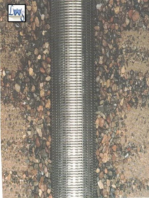
Figure 2: Wire-wrapped well screen with gravel pack.
WELL SCREEN
Maybe the most important design in a well is the screened section because you want the well to both (a) operate at its maximum efficiency to draw aquifer groundwater into the well and (b) provide representative water quality data from the groundwater aquifer. The well screen design and the aquifer matrix dictates the selection of gravel pack. The gravel pack that surrounds the well screen needs to be coarser than the formation, and it must have a relatively uniform grain size to allow water to enter the well easily while also filtering finer material from the formation. The size of the well screen opening (slot size) needs to be adequately designed to minimize the movement of gravel pack through the screen while, at the same time, preventing the adjacent formation sediments from getting into the well. A commonly-used well screen is a wire-wrapped screen, as shown in Figure 2.
GRAVEL PACK AND GROUT
Well gravel pack and the grout seal are installed in the well using a tremie pipe, i.e., a pipe inserted down the annular space so the gravel pack/grout materials can be placed directly, thereby minimizing the potential for materials bridging. Bridging is when gravel pack materials get caught in the annular space before reaching the bottom, creating pockets with no gravel pack. A fine sand pack is typically placed on top of the gravel pack to provide a transition from the coarser gravel pack to the grout seal so grout infiltration into the gravel pack is minimized.
The grout seal in the annular space is placed on top of the fine sand pack to prevent the intermingling of different water sources and any vertical percolation of water or contaminants. The material used for the seal can be any long-term stable low permeability material; however, it is typical in large diameter production wells to use cement; in smaller diameter monitoring wells, it is typical to use a combination of hydrated bentonite pellets, which is an expanding clay seal, and a cement seal. Cement mixed with water causes an increase in temperature due to the heat of hydration and may impair the integrity of the well or the grout itself. Improper installation of the well seals, such as poor contact between the borehole wall and the casing, or cracks from the heat of hydration could allow water or contaminants to percolate into the gravel pack or along the well casing and finally into the well.
While it is important to pay close attention to the completion of the well downhole so water quality and quantity is not impaired, it is also important that the well is properly sealed at the surface so to minimize the potential for the well casing to be a conduit for surface water to enter the well and contaminate the groundwater. The surface casing and seal prevents unwanted access to the well, maintains a continuous seal with the downhole grout, and prevents surface water from entering the casing. The installation of a pitless adapter at the surface can provide the sanitary seal for a potable water supply well.
Once the well is installed, it is necessary to sufficiently develop the well to remove any additives associated with drilling and provide unobstructed flow through the well - watch for a future blog for further discussion on well development.
Fundamental know-how and experience are key to successful planning and designing of a groundwater well. Either for large-scale production or water level and quality sampling, engineers and hydrogeologists at LWS have the expertise! LWS team members have been involved in numerous projects requiring the installation of production wells for municipal use and monitoring well networks that entail specific groundwater horizons to be monitored and water quality parameters to be sampled and analyzed.
Please contact LWS at 303-350-4090 or lws@lytlewater.com if you have any questions regarding the design and installation of groundwater wells, or if you need assistance with groundwater water quality sampling.
Chris Fehn, P.E., P.G., Senior Project Engineer, chris@lytlewater.com
Dan Rowe, Staff Engineer, dan@lytlewater.com